 and
and 


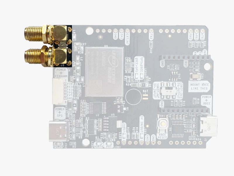
simpleRTK3B Compass does not include, but requires a good quality GPS/GNSS antenna.
simpleRTK3B Compass supports full L1/L2/L5 bands. If you want to get the most out of this module, we recommend a Triple Band simpleANT3B series antenna.
The board is compatible with both active antennas supporting 3.3V supply and passive antennas. The maximum output current is 150mA @ 3.3V.
If you use it with the traditional cheap GPS antennas widely available, you will not achieve the expected performance.
IMPORTANT: The installation of the antenna is also a key point to achieve the best results.
- It is mandatory to connect the antenna before powering the board.
- The GPS/GNSS antenna should always be installed with the maximum possible view of the sky.
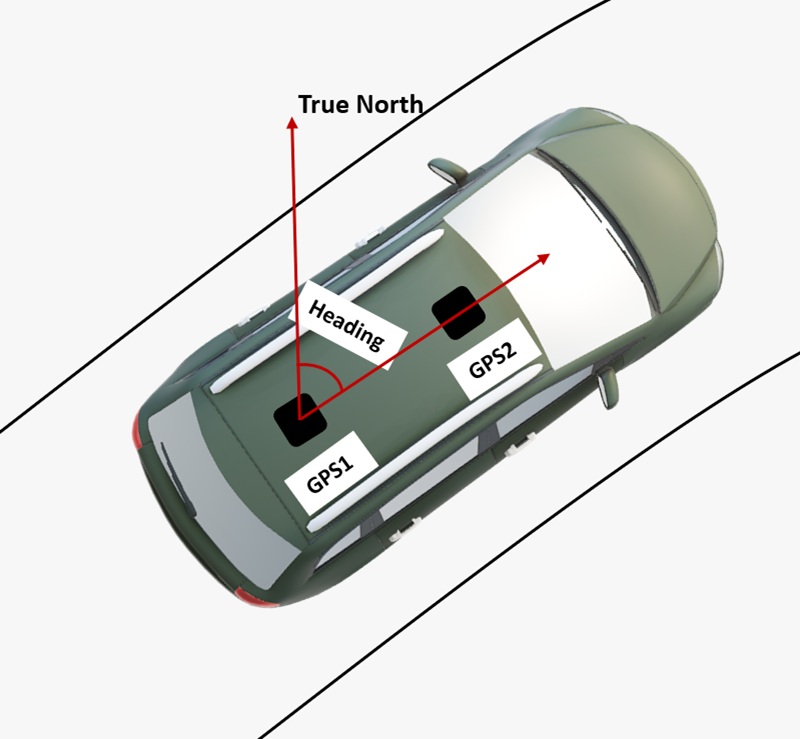
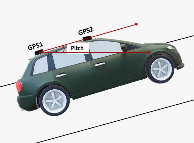
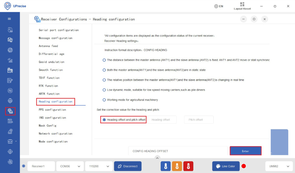
- In the default configuration, the antennas should be placed longitudinally along the vehicle, with the master antenna (GPS1) positioned at the back.
- In addition, if possible, it should be installed with a metallic plane behind, e.g. rooftop of the car, on a metal plate bigger than 20cm, etc.
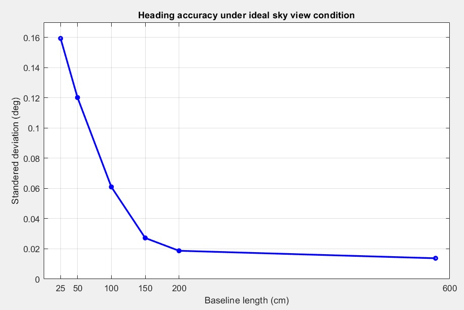
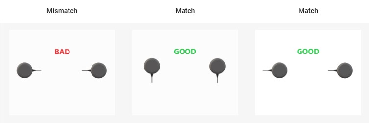
- The heading accuracy will depend on antenna distance, check image below. With a good installation with 0.5 meters, you can get decent results.
If you want to learn how installation impacts performance, please have a look at our GPS/GNSS antenna installation guide or look this video.
-

-
-
- Plugins
Radio module Long Range (LR)
101,00€ This product has multiple variants. The options may be chosen on the product page - Plugins
Radio module eXtra Long Range (XLR)
161,00€ This product has multiple variants. The options may be chosen on the product page -
-
- Sale!Made in Europe
- Sale!Plugins
4G NTRIP Master
156,00€ This product has multiple variants. The options may be chosen on the product page -
- Sale!
-

