and
and 
User Guide: simpleRTK3B Fusion
Product Overview
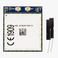
The main component of simpleRTK3B Fusion is Unicore UM981 module. The on-board INS (Inertial Navigation System) improves GNSS-only performance by providing not only position, but also attitude (roll, pitch, yaw) of the vehicle.
The board comes preloaded with firmware designed for ground vehicles, such as slow-moving tractors, cars, or ground robots. If you intend to use it for tilt-compensated surveys, you’ll need to upload the firmware for survey and mapping and at documentation section refer to the Slant Reference Commands Manual for setup instructions.
Hardware
Pinout definition
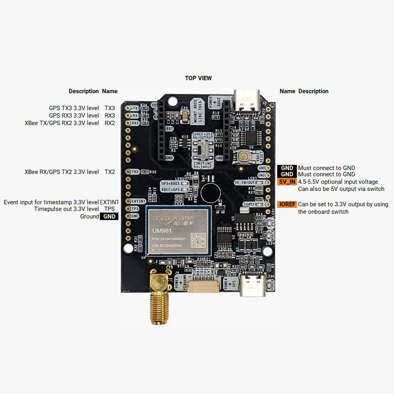
Power
The simpleRTK3B Fusion can be powered from 4 different sources:
- GPS USB port
- XBEE USB port
- Pixhawk connector
- Arduino rail
Only 1 of them is needed to use the board, but you can also connect the 4 at the same time, there’s no risk.
Communication ports
simpleRTK3B Fusion board has a few interfaces that we will now explain in detail.
USB GPS
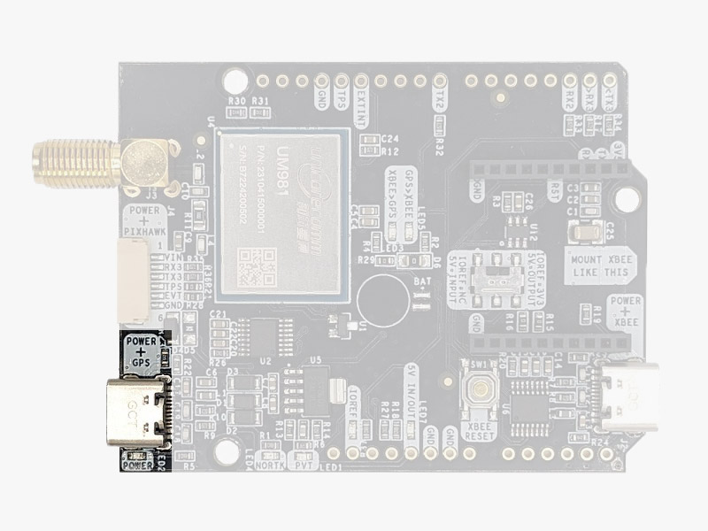
This USB-C connector gives you access via FTDI USB-to-UART converter, to COM1 of the UM980 module.
You can connect this interface to your preferred mobile phone, tablet, or PC and start receiving NMEA data.
After connecting the receiver to the PC, you will see 1 new COM ports, that you can use with your favorite terminal tool to read NMEA or have full access to the UM980 using the UPrecise tool.
By default NMEA is disabled on this module so we recommend you to start with the UPrecise tool.
If your PC doesn’t recognize the device, you will need the VCP driver from FTDI: https://ftdichip.com/drivers/vcp-drivers/
USB XBee
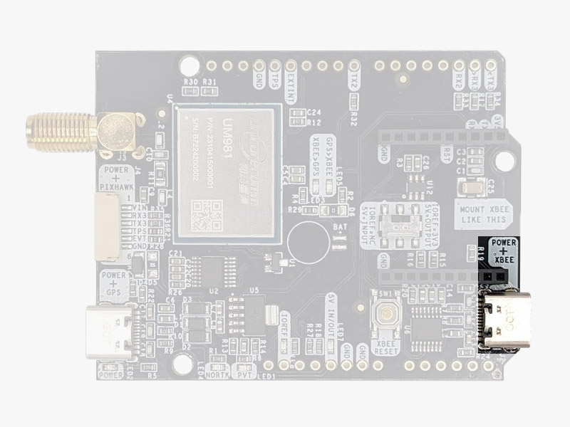
This USB-C connector gives you access to the UART of the XBEE radio (if you mount one), via an FTDI USB-to-UART converter.
We find very practical to use this connector to power the board, so you can then connect and disconnect the GPS USB as your wish, without removing the power to the board.
You can use any USB wall plug adapter you find at home.
To use this connector only as a power source, you don’t need any driver. You can use your PC, or connect to your USB wall adapter.
To use this connector to configure an XBee radio, you will need the VCP driver from FTDI: https://ftdichip.com/drivers/vcp-drivers/
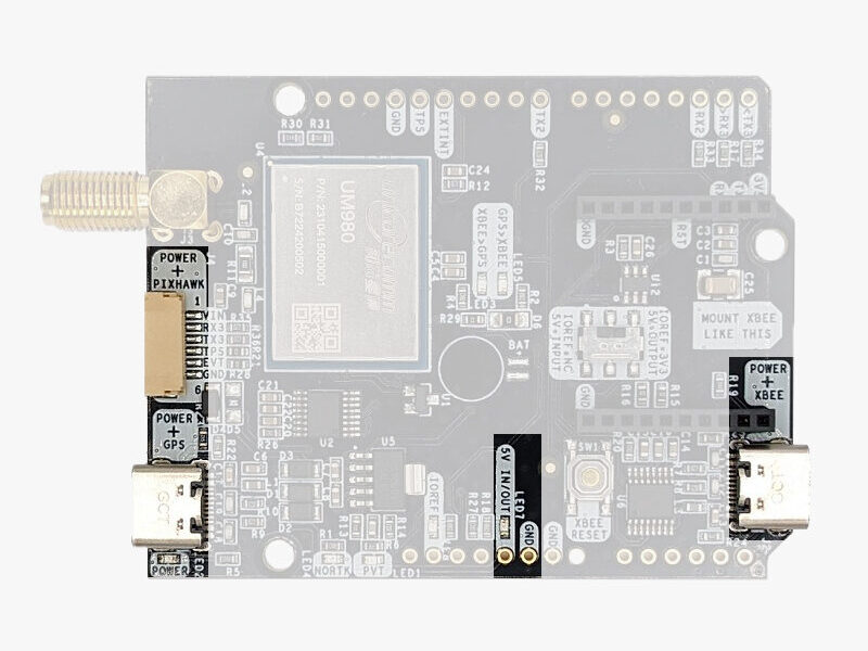
Pixhawk connector
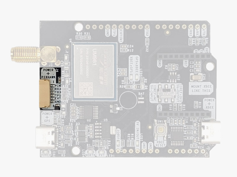
This connector is a standard JST GH that can be used to connect the simpleRTK3B Fusion to a Pixhawk autopilot.
You can also use this connector to power the board.
The Pixhawk JST-GH connector is following the Pixhawk standard:
- 1: 5V_IN
- 2: Unicore COM3 RX (3.3V level)
- 3: Unicore COM3 TX (3.3V level)
- 4: Timepulse output (3.3V level)
- 5: Extint (3.3V level)
- 6: GND
Arduino rails
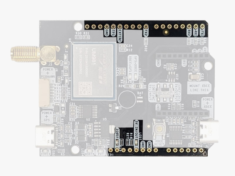
simpleRTK3B Fusion has optional rails to connect to other arduino UNO compatible devices.
- GND: ground is available in the standard arduino pins. You should always connect this line to your other board.
- 5V IN/OUT:
- When the LED next to this pin is OFF, can power simpleRTK3B Fusion from this pin.
For example, just plug it on top of an Arduino UNO board, and simpleRTK3B Fusion will turn ON. (check if your arduino can power 300mA @ 5V shields). - Alternatively, you can now use simpleRTK3B Fusion to power other shields.
Just turn ON the switch “5V=OUTPUT” and simpleRTK3B Fusion board will output 5V at this pin.
- When the LED next to this pin is OFF, can power simpleRTK3B Fusion from this pin.
- IOREF: This pin is disconnected when the onboard switch is towards “IOREF = NC”.
Alternatively it outputs 3.3V when the onboard switch is towards “IOREF = 3V3”. You can use this functionality to provide a voltage reference to other Shields that require this pin as an input. - TX2,RX2,TX3,RX3:These pins work as an output at 3.3V, and as an input accepting from 2.7 to 3.6V.
- TX2: Unicore COM2 TX (this pin is also connected to XBee UART RX)
- RX2: Unicore COM2 RX (this pin is also connected to XBee UART TX)
- TX3: Unicore COM3 TX
- RX3: Unicore COM3 RX
High Power (HP) XBee socket
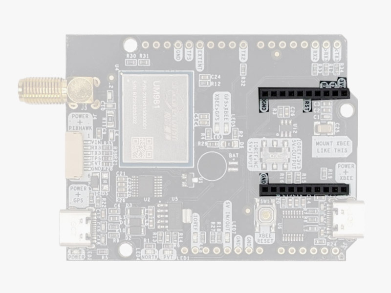
You can use this socket to connect an XBee compatible radio. The following pins are available:
- VCC, which is a 3.3V output with maximum current 1A constant and peak 1.5A.
- XBee UART RX, at 3.3V level
- XBee UART TX, at 3.3V level
- GND
Remember that you can add a second XBee socket to your board with the Shield for Second XBee socket.
Special function pins
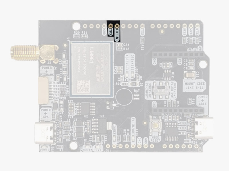
In addition to above, there’s also a few additional pins available for the most advanced users. These pins are also available in the JST connector, as in the simpleRTK3B Pro.
If you are going to use simpleRTK3B Fusion connected on top of an Arduino or Raspberry Pi and you don’t use any of these pins, it’s recommended to not connect the pins: you can cut the header in this pins to avoid the connection, and prevent unexpected behaviors.
- Timepulse (TPS): 3.3V configuration time pulse output.
- Extint (EXTINT): time synchronization input, maximum voltage 3.6V.
This input is filtered to avoid glitches.
Remember that you can add a second XBee socket to your board with the Shield for Second XBee socket.
GPS/GNSS Antenna
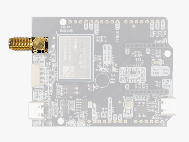
simpleRTK3B Fusion does not include, but requires a good quality GPS/GNSS antenna.
simpleRTK3B Fusion supports full L1/L2/L5 bands. If you want to get the most out of this module, we recommend a Triple Band simpleANT3B series antenna.
The board is compatible with both active antennas supporting 3.3V supply and passive antennas. The maximum output current is 150mA @ 3.3V.
If you use it with the traditional cheap GPS antennas widely available, you will not achieve the expected performance.
IMPORTANT: It is mandatory to connect the antenna before powering the board.
The installation of the antenna is also a key point to achieve the best results. The GPS/GNSS antenna should always be installed with the maximum possible view of the sky.
In addition, if possible, it should be installed with a metallic plane behind, e.g. rooftop of the car, on a metal plate bigger than 20cm, etc.
If you want to learn how installation impacts performance, please have a look at our GPS/GNSS antenna installation guide or look this video.
LEDs
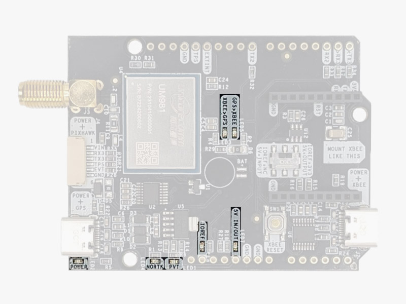
- POWER: the simpleRTK3B Fusion board has power.
- PVT: LED lights when it was possible to calculate a position from the available satellite visibility.
- NORTK: ON when no RTK, OFF when device is in RTK FIXED mode.
- XBEE>GPS: The XBEE radio is receiving data over the air and sending it to the Unicore.
- GPS>XBEE: The Unicore is outputting data to the XBee radio.
- 5V IN/OUT: Indicates if there is voltage on that pin.
- IOREF: Indicates if there is voltage on that pin.
Buttons and switches
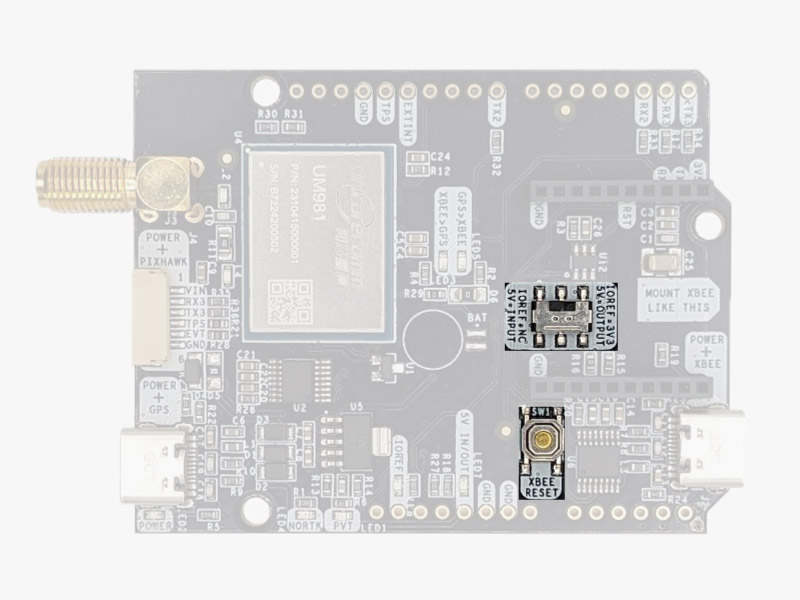
There’s only one button: XBee Reset, and the good news is that you probably will not have to use it. This button is used to program the XBee radio if you want to update firmware, etc.
You will find also 1 switch under the XBee socket: it let you enable IOREF with 3.3V and 5V arduino pin as output so the board can power accessories like Shield for Second XBee socket. At the same time this switch will also enable the arduino rail signals at 3.3V. Check the “Arduino Rails” section above to read more details about this.
Get started
Connect to UPrecise
- Connect the GNSS antenna to your receiver. Make sure the antenna has a good view of the sky for testing functionality. Or you won’t see satellites view and signal.
- Connect the receiver to your PC via the USB port labelled as POWER+GPS.
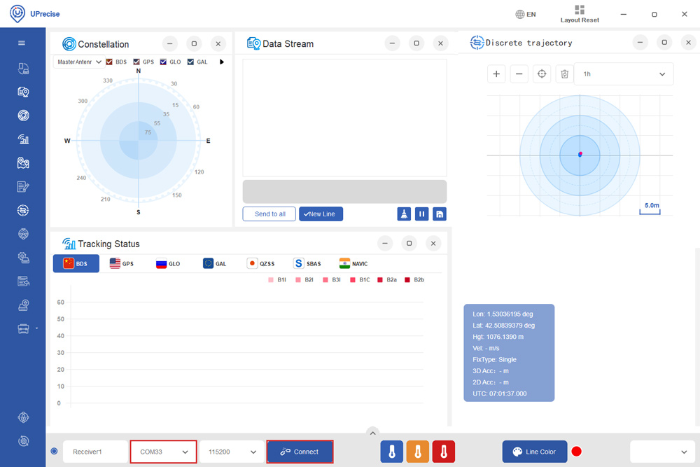
- Open Uprecise. Select the COM port (If you don’t know which COM port check the device manager of your PC). At baud rate choose 115200 or AUTO. Press Connect.
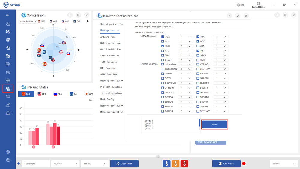
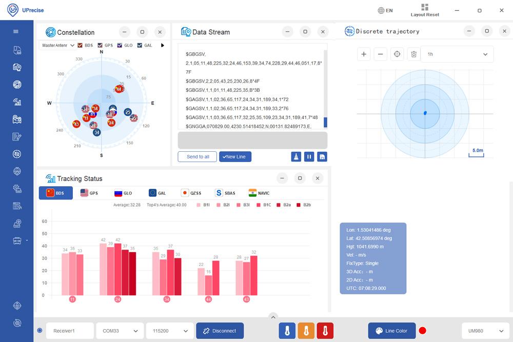
- Click the Receiver Configuration icon on the left side menu bar. Here you can enable you preferred NMEA messages ( By default NMEA is disabled on this module). We recommend checking GGA, GSA, GSV, GST and RMC. It will work well with SW Maps and most applications. Then click Enter.
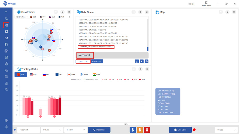
- At Menu bar choose the Data Stream icon. At Data Stream window type in SAVECONFIG and press Enter. On the Data Stream you will see Command, SAVECONFIG, response: OK. It means your configuration is saved to the Flash of your receiver.
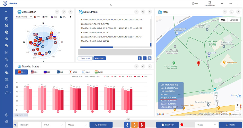
- You will see the Constellation, Data Steam and Tracking Status on the screen.
Send NMEA messages to Xbee Socket
- The Xbee socket is connected to Unicore COM2. If you want to connect with Bluetooth, BLE, radio or other communication plugins, you need to enable NMEA messages on COM2.
- For example if you want to send GGA to COM2, at the commend window type in GPGGA COM2 1. It will output 1Hz GGA message at COM2.
- Repeat the same for the NMEA messages you need. We recommend to enable GGA, GSA, GSV, GST and RMC. It will work well with SW Maps and most applications.
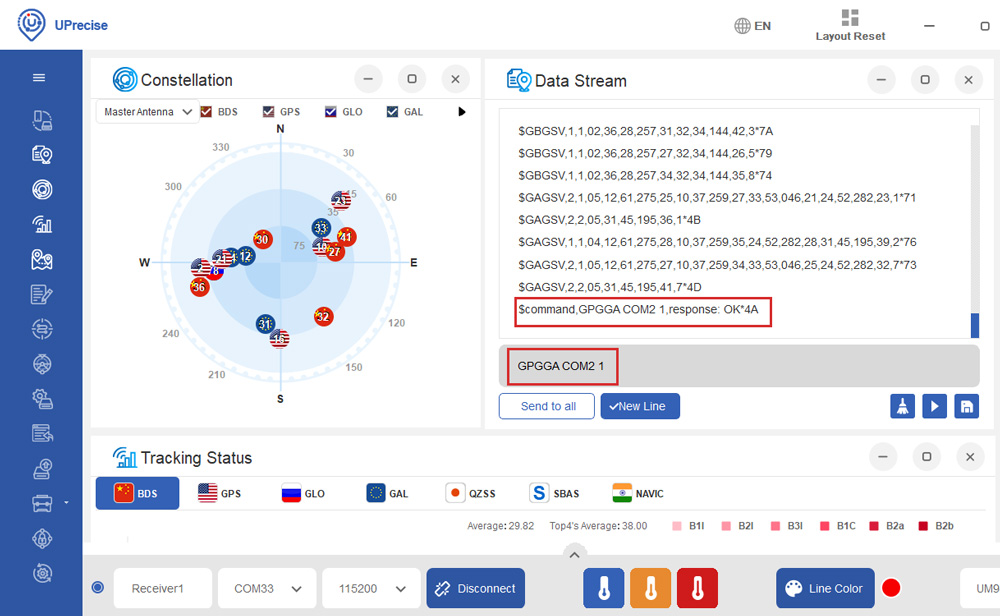
- At the commend window type in SAVECONFIG, then press Enter to save current configuration into memory.
Connect to NTRIP
In order to achieve centimeter/millimeter level accuracy with our GNSS receivers, you need to have corrections.
If you don’t have your own base station for corrections, you can find third party base stations at RTK Correction Services in your Country.
- Click the toolbox icon and select RTCM.
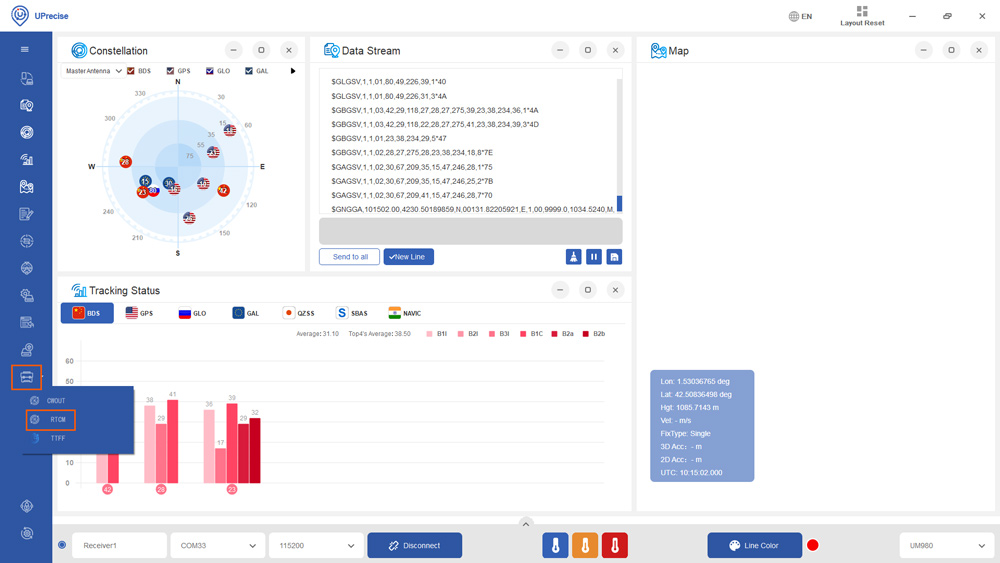
- Click Input. Choose Ntrip Client. Set your Ntrip Caster Host, Port, Mount point, ID and Password. If your Ntrip Caster need the location of your rover, set GGA Location reporting at 1, and select CurrentSerialGGA. Click Ok.
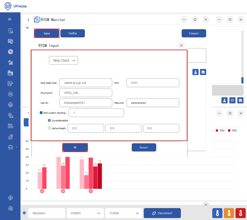
- Click the OutPut. Select Serial Port, and choose the COM port of your receiver.
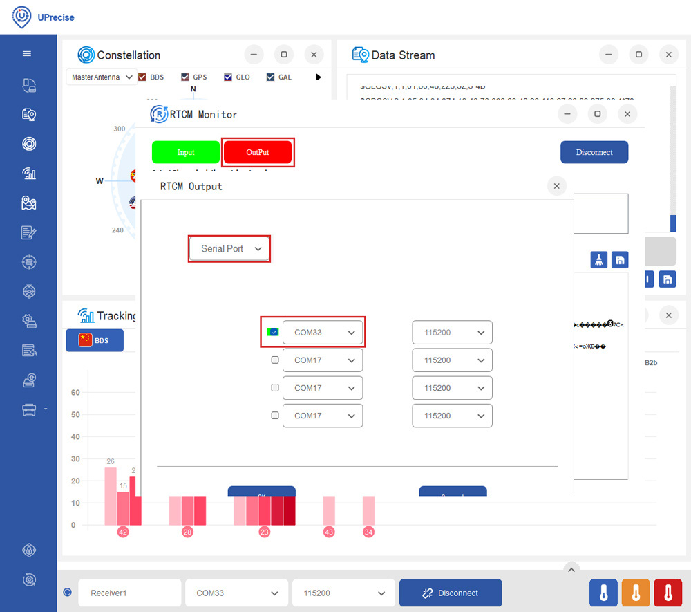
- You will see the Input and OutPut change into green. Check Hex, you will see the RTCM messages from the server.
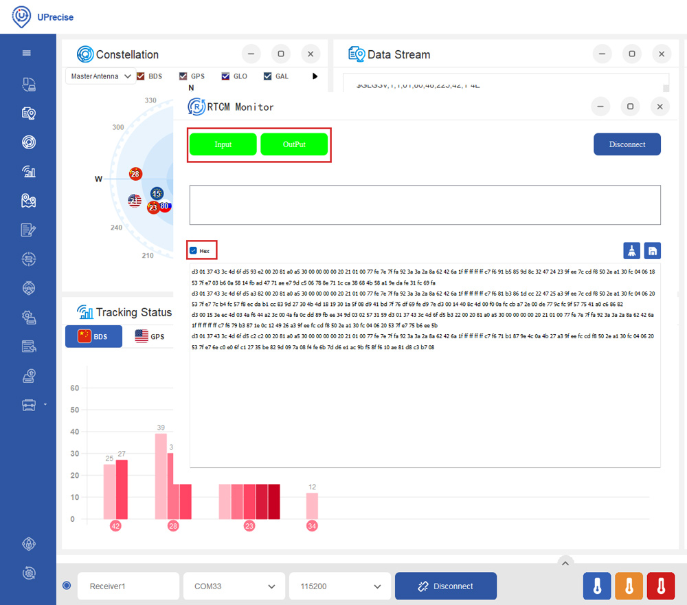
- In a few minutes, you will see the Fix Type change to RTK Float or Fixed.
Enable Galileo HAS
The Galileo High Accuracy Service (HAS) provides free of charge access, through the Galileo signal (E6-B) and by terrestrial means (Internet), to the information required to estimate an accurate positioning solution using a Precise Point Positioning algorithm in real-time.
Galileo HAS is available on simpleRTK3B Budget and simpleRTK3B Compass. It is not supported with the current firmware version of simpleRTK3B Fusion.
- Type in the following commands one by one to enable HAS.
CONFIG PPP ENABLE E6-HAS
CONFIG PPP DATUM WGS84
CONFIG PPP CONVERGE 50 50
CONFIG SIGNALGROUP 2 (Use this command if you have a simpleRTK3B Budget)
CONFIG SIGNALGROUP 3 6 (Use this command if you have a simpleRTK3B Compass)
SAVECONFIG
- In a few minutes you should see the fix type change to Float.
If you want to disable PPP, type in command:
CONFIG PPP DISABLE
And use command CONFIG PPP ENABLE E6-HAS to enable it again.
Configure inertial sensor fusion
simplertk3B Fusion has inertial sensor fusion capability, thanks to the integrated INS (Inertial Navigation System) in UM981 module. The Inertial Navigation System uses accelerometers and gyroscopes of IMU (Inertial Measurement Unit) to calculate position, velocity, and orientation.
INS is especially helpful when navigating in tunnels, measuring tilt, or moving over uneven terrain—any situation where GNSS signals may be unreliable.
Installation
- SimpleRTK3B Fusion must be fixed to the vehicle, it can’t be used hanging from the cable. This is because we need the IMU data to be consistent.
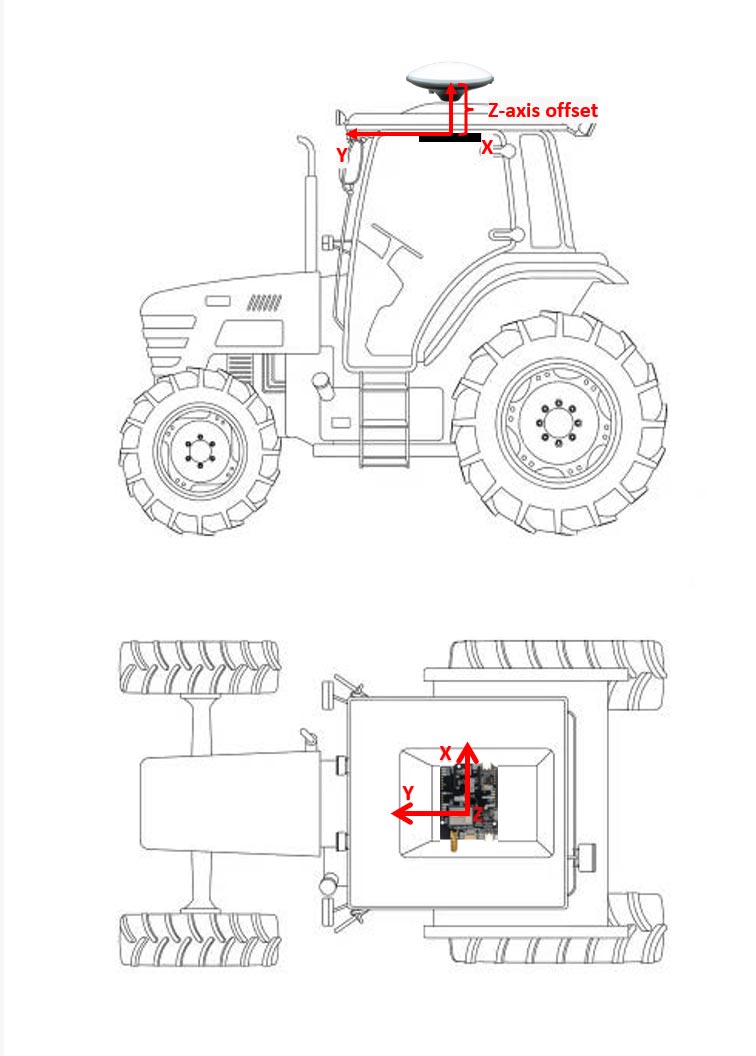
- Ensure that the IMU data remains consistent by properly mounting the receiver to your vehicle. When attaching the receiver, verify that the XYZ axis directions printed on the UM981 module align with the vehicle’s coordinate system. The coordinate system follows the right-hand rule, with the Y direction representing the forward direction of the vehicle. There are options to mount simpleRTK3B Fusion in different orientation, but this requires some extra calibration. This is why we suggest using the same orientation.

- The farther the IMU is from the antenna, the lower the accuracy. For these reasons, we recommend to mount the board under the roof of the vehicle, directly beneath the antenna. The phase center of antenna should align with the IMU of the UM981 module (located at the center of the coordinate system marked on the UM981 module). This setup ensures that only the Z-axis offset (level arm distance) needs to be measured.
Configure lever arm
- Lever arm distance is the distance between IMU and phase center of the GNSS antenna.You can use the command CONFIG IMUTOANT OFFSET x y z a b c to configure lever arm.
| Log Header | Parameter | Description |
|---|---|---|
| CONFIG IMUTOANT OFFSET | x | X-axis offset, unit: meter, range: -100~100 |
| y | Y-axis offset, unit: meter, range: -100~100 | |
| z | Z-axis offset, unit: meter, range: -100~100 | |
| a | Error of the X-axis offset, unit: meter, range: 0.01~10 (default: from 0.01m to 10% of the X-axis offset) | |
| b | Error of the Y-axis offset, unit: meter, range: 0.01~10 (default: from 0.01m to 10% of the Y-axis offset) | |
| c | Error of the Z-axis offset, unit: meter, range: 0.01~10 (default: from 0.01m to 10% of the Z-axis offset) |
- Based on the given example of step 20, if the Z-axis offset is 20cm, the command will be:
CONFIG IMUTOANT OFFSET 0 0 0.20 0.01 0.01 0.01
Note that if you are using a multiband antenna with multiple phase centers for different frequencies (L1 and L2), use the median value.
Configure the alignment speed threshold
Inertial navigation systems rely on accelerometers and gyroscopes to track movement. The INS Alignment Speed Threshold is the minimum speed at which an inertial navigation system can perform an accurate alignment. This alignment is crucial for determining the initial position and orientation of the system before it can provide reliable navigation data.
- You can use the command: CONFIG INS ALIGNMENTVEL 5.0 to set the speed threshold for INS alignment in 5 m/s. Note that the default alignment speed is 5 m/s, and the minimum is 0.5 m/s.
Enable/Disable INS
- The INS function of simpleRTK3B Fusion is enabled by default. Users can input the command CONFIG INS DISABLE to disable INS.If INS needs to be enabled again, use the command CONFIG INS RESET to enable INS and reset INS to the unaligned state.
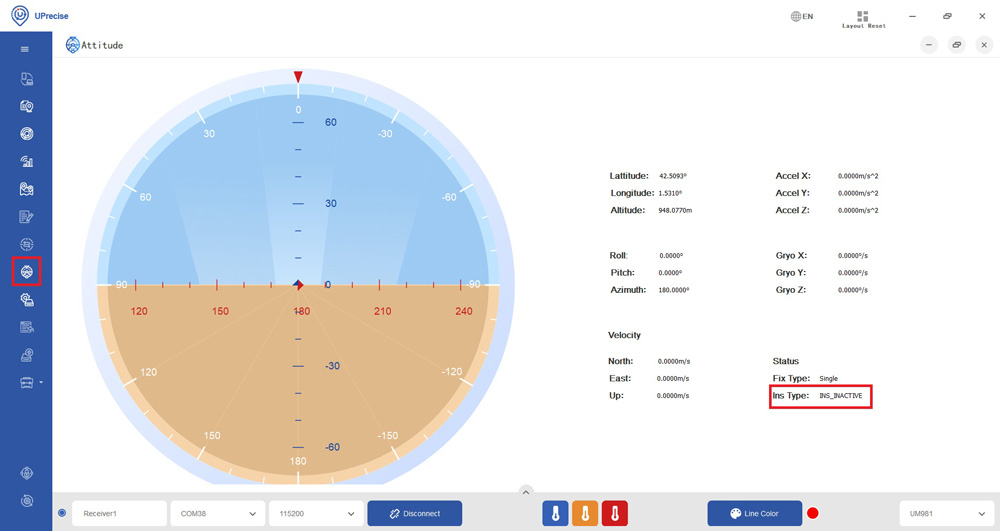
INS alignment initialization
- You can check the vehicle attitude and INS type at Attitude–>Status–>Ins Type.
|
Decimal
|
ASCII
|
Description
|
|---|---|---|
|
0
|
INS_INACTIVE
|
IMU data invalid; INS inactive
|
|
1
|
INS_ALIGNING
|
INS is aligning
|
|
2
|
INS_HIGH_VARIANCE
|
INS is in navigation mode, but the error of azimuth has exceeded the threshold. For most IMUs, the default threshold is 2 degrees.
|
|
3
|
INS_SOLUTION_GOOD
|
Entered the navigation mode and the INS solution is good
|
|
6
|
INS_SOLUTION_FREE
|
DR mode, no GNSS participated in the integrated solution
|
|
7
|
INS_ALIGNMENT_COMPLETE
|
INS alignment completed, but not enough vehicle dynamics to make the accuracy meet the requirement.
|
- After the module outputs the fixed solutions, drive forward at a speed greater than the alignment speed threshold set in step 23. During this process, the Ins Type will display as INS_ALIGNING. Once the INS alignment is complete, the Ins Type will update to INS_ALIGNMENT_COMPLETE. Continue driving at a speed exceeding the alignment threshold for 15 seconds until the solution status changes from INS_ALIGNMENT_COMPLETE to INS_SOLUTION_GOOD, indicating that the initialization process is complete.
Fusion mode (GPS+IMU) message output
- You can use the command INSPVAXA 1 to enable INSPVAXA message at 1Hz. This log is used to output the integrated position, velocity, attitude and their estimated errors. Message Output example: #INSPVAXA,COM1,0,73.5,FINESTEERING,1695,309428.000,00000040,4e77,43562; INS_SOLUTION_GOOD,INS_PSRSP,51.11637873403,-114.03825114994,1063.6093,- 16.9000,-0.0845,-0.0464,-0.0127,0.138023492,0.069459386,90.000923268,0.9428, 0.6688,1.4746,0.0430,0.0518,0.0521,0.944295466,0.944567084,1.000131845,3,0*e877c 17
| ID | Field Type | Data Description | Format | Binary Bytes | Binary Offset |
|---|---|---|---|---|---|
| 1 | INSPVAX | Log header | H | 0 | |
| 2 | INS Status | INS status, see step 26, INS Type | Enum | 4 | H |
| 3 | Pos Type | Position type | Enum | 4 | H+4 |
| 4 | Latitude | Latitude (WGS84) [degrees] | Double | 8 | H+8 |
| 5 | Longitude | Longitude (WGS84) [degrees] | Double | 8 | H+16 |
| 6 | Height | Height [m] | Double | 8 | H+24 |
| 7 | Undulation | Geoidal separation: the difference between the mean-sea-level (geoid) surface and the WGS84 ellipsoid surface, in meters. If the geoid is above the ellipsoid, the value is positive; otherwise, it is negative. | Float | 4 | H+32 |
| 8 | North Velocity | Velocity in a northerly direction (negative implies south) [m/s] | Double | 8 | H+36 |
| 9 | East Velocity | Velocity in an easterly direction (negative implies west) [m/s] | Double | 8 | H+44 |
| 10 | Up Velocity | Velocity in an up direction [m/s] | Double | 8 | H+52 |
| 11 | Roll | Roll (right-handed rotation around Y axis) [degrees] | Double | 8 | H+60 |
| 12 | Pitch | Pitch (right-handed rotation around X axis) [degrees] | Double | 8 | H+68 |
| 13 | Azimuth | Azimuth, clockwise from north (left-handed rotation around Z axis) [degree]. This is the inertial azimuth calculated from the IMU gyros and integrated filters. | Double | 8 | H+76 |
| 14 | Lat σ | Standard deviation of latitude [m] | Float | 4 | H+84 |
| 15 | Long σ | Standard deviation of longitude [m] | Float | 4 | H+88 |
| 16 | Height σ | Standard deviation of height [m] | Float | 4 | H+92 |
| 17 | North Vel σ | Standard deviation of north velocity [m/s] | Float | 4 | H+96 |
| 18 | East Vel σ | Standard deviation of east velocity [m/s] | Float | 4 | H+100 |
| 19 | Up Vel σ | Standard deviation of up velocity [m/s] | Float | 4 | H+104 |
| 20 | Roll σ | Standard deviation of roll [degrees] | Float | 4 | H+108 |
| 21 | Pitch σ | Standard deviation of pitch [degrees] | Float | 4 | H+112 |
| 22 | Azimuth σ | Standard deviation of azimuth [degrees] | Float | 4 | H+116 |
| 23 | Ext sol stat | Extended solution status | Hex | 4 | H+120 |
| 24 | Time Since Update | Time elapsed since the last ZUPT or position update (seconds) | Ushort | 2 | H+124 |
| 25 | xxxx | 32-bit CRC | Hex | 4 | H+126 |
| 26 | [CR][LF] | Sentence terminator (ASCII only) | - | - | - |
Documentation
If you are an advanced user looking to configure your receiver according to your specific needs or to program it for your project, please refer to the following documents.
- If you need additional information, such as upgrading firmware, configuring the receiver as a base or rover please refer to the Unicore configuration page.
- If you need to check Unicore command for your project or configure the receiver check Unicore Reference Command Manual.
- If you want to use simpleRTK3B Fusion for tilt compensation with your survey, check Slant Reference Commands Manual.
- If you want to use simpleRTK3B Fusion for your farm machinery, check Auto Reference Commands Manual.
Accessories
You can add any of these features (and more) with our XBee plugins:
-

-
-
-
 Plugins
Radio module Long Range (LR)
101,00€ This product has multiple variants. The options may be chosen on the product page -
 Plugins
Radio module eXtra Long Range (XLR)
161,00€ This product has multiple variants. The options may be chosen on the product page -
-
-
Sale!
 Made in Europe
 -
Sale!
 Plugins
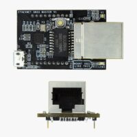
4G NTRIP Master
156,00€ This product has multiple variants. The options may be chosen on the product page -

-
Sale!
-