Update (22/10/2024): We have plenty of stock of all our products, find us also in and    Shop now

User Guide: simpleRTK3B Pro

Product Overview

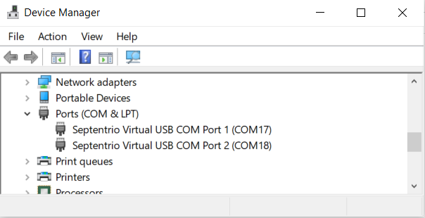
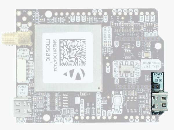
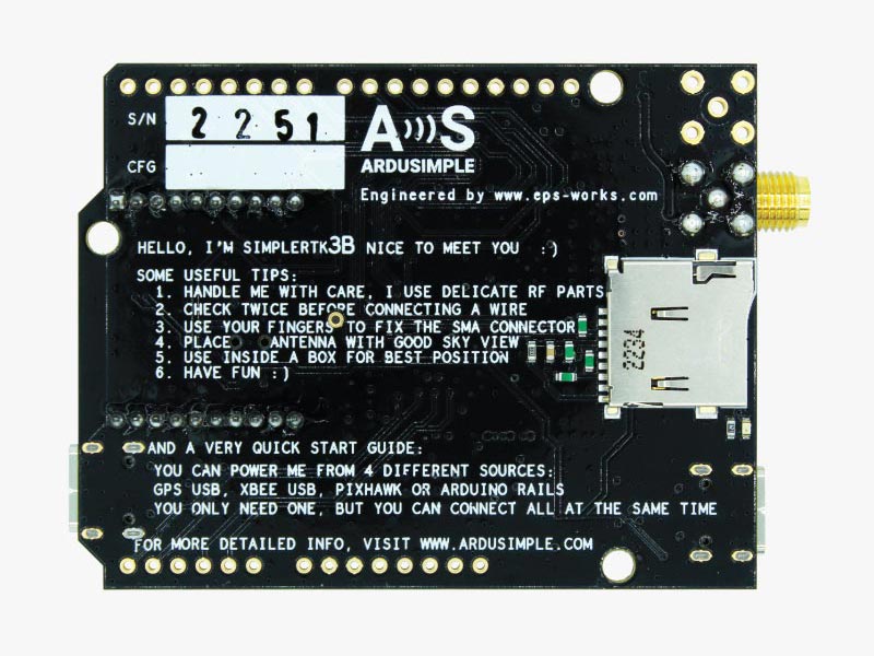
You can use simpleRTK3B Pro as a standalone board by connecting it to your PC or tablet. Additionally, it can be used as an add-on board for your projects, such as an Arduino shield.
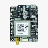
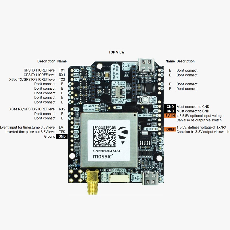
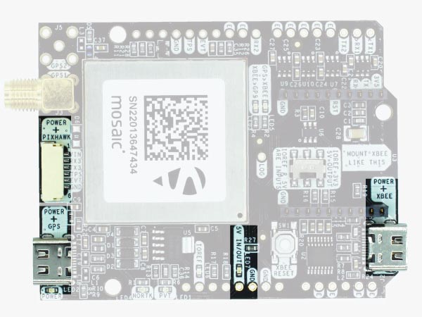
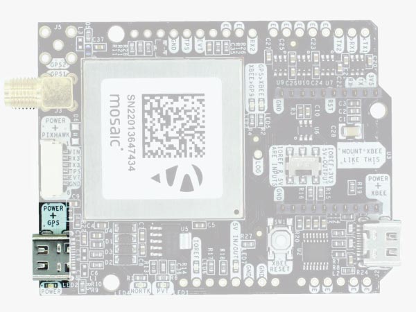
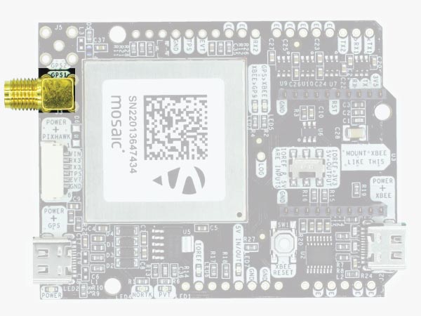
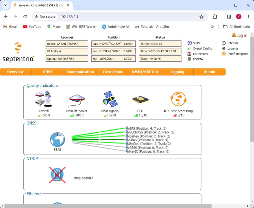
The main component of simpleRTK3B Pro is Mosaic-X5 Triple Band (L1/L2/L5) RTK GNSS module.
Important before use :
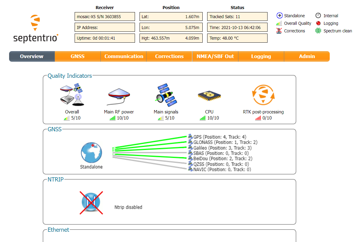
This is a traditional RTK module, it only finds satellites outdoors. If you try to use it next to the Window it will not find any satellites.
The module needs 10 seconds to boot, be patient after connecting to the PC 🙂

Hardware

Pinout definition

Power

The simpleRTK3B Pro can be powered from 4 different sources:
  • GPS USB port
  • XBEE USB port
  • Pixhawk connector
  • Arduino rail
Only 1 of them is needed to use the board, but you can also connect the 4 at the same time, there’s no risk.
The simpleRTK3B Pro has a High Power (HP) XBee socket. You can connect any XBee accessory to it. If you connect a device that requires high power to the XBee socket, you will have to make sure your power supply can provide this power.
  • Use only high quality USB-C cables, not longer than 1 meter.
  • If you connect simpleRTK3B Pro through a USB hub to your PC/Tablet or your PC has low power USB ports, you will have to connect the second USB port directly to a wall plug or high power USB port.

Communication ports

simpleRTK3B Pro board has a few interfaces that we will now explain in detail.

USB GPS
This USB-C connector gives you access to the native USB from the Mosaic module. When you connect to the PC for the first time, you will only see a new Hard Disk in your computer. Open it and install the Septentrio drivers.
After installation, when you connect the receiver to the PC, you will see 2 new COM ports, that you can use with your favourite terminal tool to read NMEA or have full access to the Mosaic using RxTools.

But the nicest thing of this receiver is that if you go to the web browser and write 192.168.3.1,  the Septentrio web interface appears, that you can both to configure and monitor the receiver:

USB XBee
This USB-C connector gives you access to the UART of the XBEE radio (if you mount one), via an FTDI USB-to-UART converter. We find very practical to use this connector to power the board, so you can then connect and disconnect the GPS USB as your wish, without removing the power to the board. You can use any USB wall plug adapter you find at home.
To use this connector only as a power source, you don’t need any driver. You can use your PC, or connect to your USB wall adapter.
To use this connector to configure an XBee radio, you will need the VCP driver from FTDI: https://ftdichip.com/drivers/vcp-drivers/
Pixhawk connector
This connector is a standard JST GH that can be used to connect the simpleRTK3B Pro to a Pixhawk autopilot. You can also use this connector to power the board.
The Pixhawk JST-GH connector is following the Pixhawk standard:
  • 1: 5V_IN
  • 2: Mosaic COM3 RX (3.3V level)
  • 3: Mosaic COM3 TX (3.3V level)
  • 4: Timepulse output (3.3V level)
  • 5: Event input (3.3V level)
  • 6: GND
Please note that the board only includes GPS and doesn’t include magnetometer.
Arduino rails
simpleRTK3B Pro has optional rails to connect to other arduino UNO compatible devices.
  • GND: ground is available in the standard arduino pins. You should always connect this line to your other board.
  • 5V IN/OUT:
    • When the LED next to this pin is OFF, can power simpleRTK3B Pro from this pin. For example, just plug it on top of an Arduino UNO board, and simpleRTK3B Pro will turn ON. (check if your arduino can power 300mA @ 5V shields).
    • Alternatively, you can now use simpleRTK3B Pro to power other shields. Just turn ON the switch “5V=OUTPUT” and simpleRTK3B Pro board will output 5V at this pin.
  • IOREF. This pins affect the functionality of TX1,RX1,TX2,RX2 pins.
    • When plugging simpleRTK3B Pro board on top of Arduino UNO or Raspberry Pi, this pin is used to automatically defined the voltage level of the communication pins (TX1,RX1,TX2,RX2).
    • When wiring your own cables to board,  this is an input that will define the voltage levels of the pins. If you input 1.8V, the next pins will be 1.8V level. It supports from 1.2V to 5.5V.
    • If you want to connect wires to the listed pins and 3.3V is OK for you, you just need to enable the switch “IOREF=3.3V”
  • TX1,RX1,TX2,RX2: These pins work with the voltage level defined by IOREF.
    • TX1: Mosaic COM1 TX
    • RX1: Mosaic COM1 RX
    • TX2: XBee UART TX (this pin is also connected to Mosaic COM2 RX).
    • RX2: XBee UART RX (this pin is also connected to Mosaic COM2 TX).
High Power (HP) XBee socket
The simpleRTK3B has a High Power (HP) XBee socket. You can use this socket to connect an XBee compatible radio. The following pins are available:
  • VCC, which is a 3.3V output with maximum current 1A constant and peak 1.5A.
  • XBee UART RX, at 3.3V level
  • XBee UART TX, at 3.3V level
  • GND
The XBee socket is connected to Mosaic COM2.
Special function pins
In addition to above, there’s also a few additional pins available for the most advanced users. If you are going to use simpleRTK3B connected on top of an Arduino or Raspberry Pi and you don’t use any of these pins, it’s recommended to not connect the pins: you can cut the header in this pins to avoid the connection, and prevent unexpected behaviors.
  • Timepulse (TPS): 3.3V configuration time pulse output. The logic of this pin is inverted with the web interface. If the web interface you select HIGH, the pin will output LOW.
  • External Event (EVT): time synchronization input, maximum voltage 3.6V. This input is filtered to avoid glitches.
  • Logging Button (LOG): the logging feature can be controlled via web interface, but in case you want to add a button to control this feature.
    • Driving the LOGBUTTON pin low for 100 ms to 5 seconds toggles logging on and off.
    • Driving the LOGBUTTON pin low for more than 5 seconds and then releasing it unmounts the SD card if it was mounted, or mounts it if it was unmounted.
Remember that you can add a second XBee socket to your board with the Shield for Second XBee socket.

GPS/GNSS Antenna

simpleRTK3B Pro does not include, but requires a good quality GPS/GNSS antenna.
simpleRTK3B Pro supports full L1/L2/L5 bands. If you want to get the most out of this module, we recommend a Triple Band simpleANT3B series antenna.
The board is compatible with both active antennas supporting 3.3V supply and passive antennas. The maximum output current is 150mA @ 3.3V.
If you use it with the traditional cheap GPS antennas widely available, you will not achieve the expected performance.
IMPORTANT: It is mandatory to connect the antenna before powering the board.
The installation of the antenna is also a key point to achieve the best results. The GPS/GNSS antenna should always be installed with the maximum possible view of the sky.
In addition, if possible, it should be installed with a metallic plane behind, e.g. rooftop of the car, on a metal plate bigger than 20cm, etc.
If you want to learn how installation impacts performance, please have a look at our GPS/GNSS antenna installation guide  or look this video.

LEDs

The board includes 7 status LEDs, which indicate that:
  • Timepulse (TPS): 3.3V configuration time pulse output. The logic of this pin is inverted with the web interface. If the web interface you select HIGH, the pin will output LOW.
  • External Event (EVT): time synchronization input, maximum voltage 3.6V. This input is filtered to avoid glitches.
  • Logging Button (LOG): the logging feature can be controlled via web interface, but in case you want to add a button to control this feature.
    • Driving the LOGBUTTON pin low for 100 ms to 5 seconds toggles logging on and off.
    • Driving the LOGBUTTON pin low for more than 5 seconds and then releasing it unmounts the SD card if it was mounted, or mounts it if it was unmounted.
  • LED: Indicates the system status. Blinks in different patterns based on various events.

Buttons and swittches

There’s only one button: XBee Reset, and the good news is that you probably will not have to use it. This button is used to program the XBee radio if you want to update firmware, etc.
You will find also 1 switch under the XBee socket: it let you enable IOREF with 3.3V and 5V arduino pin as output so the board can power accessories like Shield for Second XBee socket.
At the same time this switch will also enable the arduino rail signals at 3.3V. Check the “Arduino Rails” section above to read more details about this.

Onboard datalogging (MicroSD card)

simpleRTK3B Pro incorporates a microSD card reader for data logging. You can configure the datalogging details from Septentrio’s web interface.

A peculiarity of Septentrio datalogging is that storage inside microSD card is done in batches. For example, if you only enable GGA message for storage 1 time per second and you only leave the system up for 10 seconds, there will be no data inside the memory card, because you didn’t reach the minimum data size for storage. We recommend enabling a few messages per second to make sure when powering down a minimum number of last messages are lost.

In case you want to control logging with a button, there’s a pin labelled LOG that is connected to the LOGBUTTON function of the Mosaic module: if you connect this pin to GND you can trigger externally start / stop of recording. Otherwise you can simply do it from the web interface or leave it always O.

Get started

Connect to Septentrio web interface
  1. Connect the GNSS antenna to your receiver. Make sure the antenna has a good view of the sky for testing functionality. Or you won’t see satellites view and signal.
  2. Connect the receiver to your PC via the USB port labelled as POWER+GPS. When you connect this product to a PC for the first time, the PC may not recognize it. you will only see a new Hard Disk in your computer. Open it and install the Septentrio driver. After installation, disconnect and reconnect again, your PC will recognize the receiver. This only need to be done once. 
  3. Open a web browser and type in 192.168.3.1
Send NMEA messages to Xbee Socket
  1. In the menu bar go to Communication–>Serial Port.
  1. Set the Baud rate of COM2 at 115’200 bps. Because most of our communication plug-in works at 115’200 bps. Press Ok and Save configuration.
  1. In the menu bar go to NMEA/SBF Out. Press +New NMEA stream–>Serial port–>COM2.
  1. At Interval choose 1 sec and check your preferred NMEA messages. If you don’t know which one to choose, we suggest to check GGA, GSA, GSV, RMC and VTG. Because they are used by most of the applications. Select these messages and press Finish. But be careful, as Bluetooth bandwidth is limited. Enabling this message will result in a maximum transmission rate of 1Hz. If you want to use at higher frequency you can use the USB connector or reduce the number of messages being transmitted to avoid exceeding the Bluetooth transmission capacity.
  1. You will observe Data Streams outputting NMEA and RTCM messages to COM2. Press Ok and Save configuration.
Connect to NTRIP

In order to achieve centimeter/millimeter level accuracy with our GNSS receivers, you need to have corrections.
If you don’t have your own base station for corrections, you can find third party base stations at RTK Correction Services in your Country. Register and get you server, port, username, password and mount point of your NTRIP correction. We will use it later.

  1. Share your internet connection with the receiver via USB and receiving RTK corrections by following the video tutorial. 
  1. You will see corrections coming in and in a few minutes, you will have RTK Float or Fixed.
    Note that when you restart or reboot the receiver, the IP address will change. You will need to check the new IP address and connect your receiver.

If you need additional information, such as upgrading firmware, configuring the receiver as a base or rover please refer to the Septentrio Configuration Page.

Accessories

You can add any of these features (and more) with our XBee plugins:

Got any questions or requests?
Contact us! We'll answer <24 hours!

Icon
Contact ArduSimple
Close

Want to learn more about GPS/RTK?

1. Our engineering team will contact you to solve any questions
2. We will keep you updated about promotions and new product releases
3.You will only hear from us when we have important news, we won’t spam your email